Electric circuits
🎯What you need to be able to do
- Draw and interpret circuit diagrams with the standard symbols, including thermistors, LDRs, relays, diodes and LEDs EXTENDED.
- Know that current is the same everywhere in a series circuit; add e.m.f.s and resistances in series.
- Know that the source current in a parallel circuit is larger than each branch current, and that two resistors in parallel have less resistance than either alone.
- Use the junction rule, the sum of p.d.s in series and the p.d. across parallel branches; calculate two resistors in parallel EXTENDED.
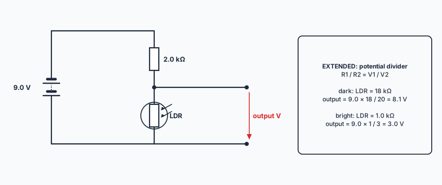
- Describe a variable potential divider and use \( \dfrac{R_1}{R_2} = \dfrac{V_1}{V_2} \) EXTENDED.
📚The physics
Series circuits
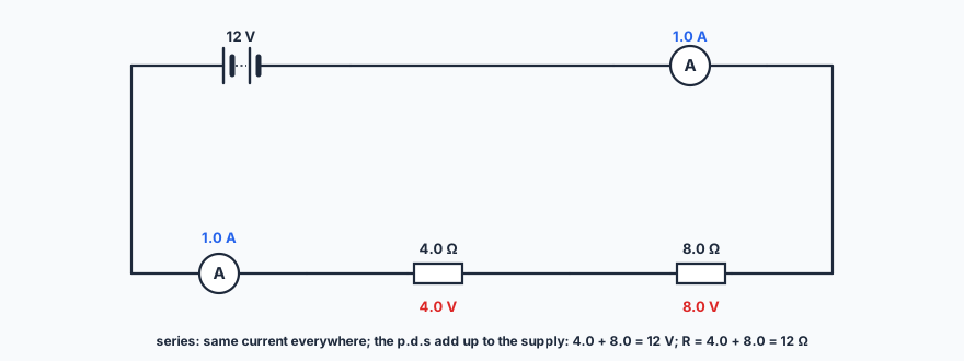
- The current is the same at every point in a series circuit.
- E.m.f.s of cells in series add (if they face the same way). Resistances in series add: \( R = R_1 + R_2 \).
- EXTENDED The total p.d. across the components equals the sum of the individual p.d.s.
- For a constant current, the p.d. across a conductor increases as its resistance increases.
Parallel circuits
- The current from the source is larger than the current in each branch. EXTENDED The sum of the currents entering a junction equals the sum leaving it (charge is not used up).
- The combined resistance of two resistors in parallel is less than that of either one. EXTENDED \( \dfrac{1}{R} = \dfrac{1}{R_1} + \dfrac{1}{R_2} \).
- EXTENDED The p.d. across each parallel branch is the same.
- Lamps in a house are connected in parallel: each gets the full mains voltage, each can be switched on and off independently, and if one fails the others stay lit.
Components
thermistor (NTC): resistance decreases as temperature increases — temperature sensors, fire alarms
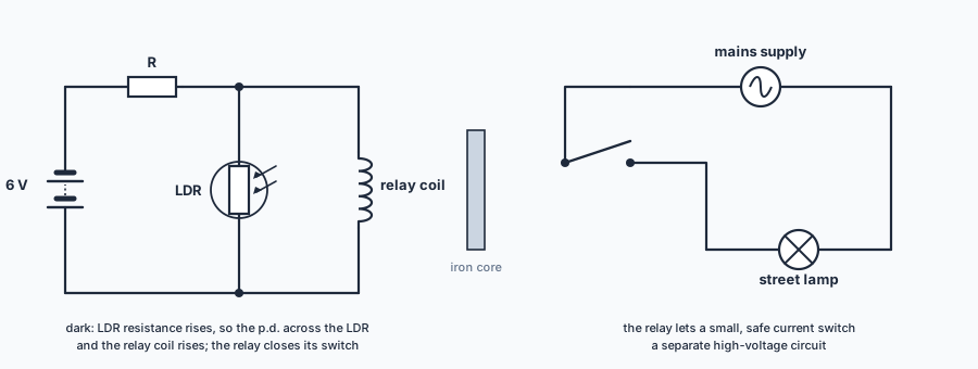
light-dependent resistor (LDR): resistance decreases as light intensity increases — automatic lights
relay: a small current in a coil makes an electromagnet close a switch in a separate circuit
EXTENDED diode: lets current flow in one direction only; LED: a diode that emits light when it conducts
Potential dividers EXTENDED
\[ \frac{R_1}{R_2} = \frac{V_1}{V_2} \]
Two resistors in series share the supply p.d. in the ratio of their resistances. Replacing one with a variable resistor, a thermistor or an LDR gives an output p.d. that changes with its setting, the temperature or the light level.
✏️Worked example
EXTENDED A 6.0 V battery is connected to a 3.0 Ω and a 6.0 Ω resistor in parallel.
(a) Calculate the current in each resistor. [2]
(b) Calculate the current from the battery. [1]
(c) Calculate the combined resistance, and check it with your answer to (b). [2]
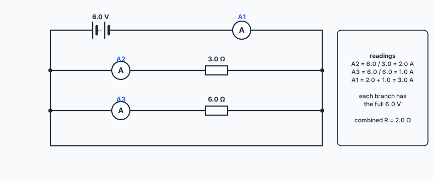
(a) Each branch has the full 6.0 V: I = 6.0 / 3.0 = 2.0 A and 6.0 / 6.0 = 1.0 A.
(b) 2.0 + 1.0 = 3.0 A.
(c) \( \dfrac{1}{R} = \dfrac{1}{3.0} + \dfrac{1}{6.0} = \dfrac{1}{2.0} \), so R = 2.0 Ω; check: 6.0 / 2.0 = 3.0 A. ✓
Check it. The combined resistance (2.0 Ω) is less than the smaller resistor (3.0 Ω), as it must be for parallel resistors.
Forgetting the last step. 1/3 + 1/6 = 1/2 gives 1/R, not R: turn it over.
📝Practise
In the style of the multiple-choice and theory papers. EXTENDED marks Supplement content.
1. (Multiple choice.) EXTENDED Two resistors in parallel have a combined resistance of 12 Ω. One is 20 Ω. What is the other? A: 8 Ω. B: 16 Ω. C: 30 Ω. D: 32 Ω. (Modelled on 0625/22 June 2026 Q29.)
C. 1/R2 = 1/12 − 1/20 = 5/60 − 3/60 = 2/60, so R2 = 30 Ω.
2. (Theory.) Three 1.5 V cells are connected in series, all the same way round. State the total e.m.f. [1]
4.5 V.
3. (Theory.) A thermistor is in series with a relay coil and a battery. The relay switches on a warning buzzer. Explain, in terms of resistance and current, why the buzzer sounds when the temperature rises. [3] (Modelled on 0625/42 June 2026 Q8(b).)
As the temperature rises the thermistor’s resistance decreases, so the current in the circuit (and relay coil) increases. The relay coil becomes a stronger electromagnet, which closes the switch in the buzzer circuit.
4. (Theory.) State two advantages of connecting house lamps in parallel rather than in series. [2]
Each lamp gets the full mains voltage (full brightness); each can be switched independently; if one fails the others stay on.
5. (Theory.) EXTENDED A 12 V supply is connected across a 4.0 kΩ and an 8.0 kΩ resistor in series. Calculate the p.d. across each. [2]
The p.d. divides in the ratio 4 : 8: 4.0 V across 4.0 kΩ and 8.0 V across 8.0 kΩ.
6. (Theory.) EXTENDED 0.60 A enters a junction. Two wires leave it; one carries 0.25 A. What is the current in the other, and why? [2]
0.35 A: the current into a junction equals the current out, because charge is conserved.
7. (Theory.) EXTENDED Explain why an LED lights when connected one way round in a circuit but not the other. [1]
An LED is a diode: it conducts in one direction only (very high resistance in reverse), so no current flows when it is reversed.
🔗Go deeper — other people’s work
These are external resources, not mine. If one stops working, tell me and everything above it on this page still stands.
- PhET “Circuit Construction Kit: DC” — build series and parallel circuits with meters
- The Physics Classroom — series and parallel circuits