Theme B · The particulate nature of matter · SL and HL
Circuits are where Theme B stops being about molecules in a box and starts being about charges in a wire — but it is the same physics. A current is a flow of particles; a potential difference is energy per unit charge; resistance is what happens when those particles keep colliding with the lattice they are moving through. Get those three definitions exactly right and every circuit question becomes bookkeeping.
🎯What you need to be able to do
Use \( I = \Delta q/\Delta t \) and \( Q = Ne \), and distinguish conventional current from electron flow.
Use \( I = nAvq \) and explain why drift speed is so small.
Define potential difference and emf as energy per unit charge, and say how they differ.
Use \( R = V/I \), and sketch and interpret the \(I\)–\(V\) characteristics of an ohmic conductor, a filament lamp and a diode.
Use \( R = \rho L/A \) and predict how resistance changes with the dimensions of a wire.
Use \( P = VI = I^{2}R = V^{2}/R \).
Combine resistors in series and in parallel, and place ideal ammeters and voltmeters correctly.
Use \( \varepsilon = I(R + r) \) for a cell with internal resistance, and find the terminal potential difference.
Analyse a potential divider.
⚡Charge and current
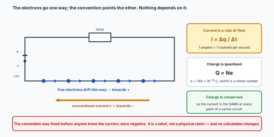
Charge is quantised: it comes in whole multiples of the elementary charge \( e = 1.60 \times 10^{-19} \) C. So any charge \(Q\) is \( Q = Ne \) for some whole number \(N\). It is also conserved — charge is never created or destroyed, only moved, which is why current is the same all the way round a series circuit.
Electric current is the rate of flow of charge:
\[ I = \frac{\Delta q}{\Delta t} \qquad \text{1 ampere} = \text{1 coulomb per second} \]
Conventional current runs from + to −; the electrons actually go the other way. The convention was fixed before anyone knew what the carriers were, and nothing in any calculation depends on it.
🐌Drift velocity: how slowly a current actually moves
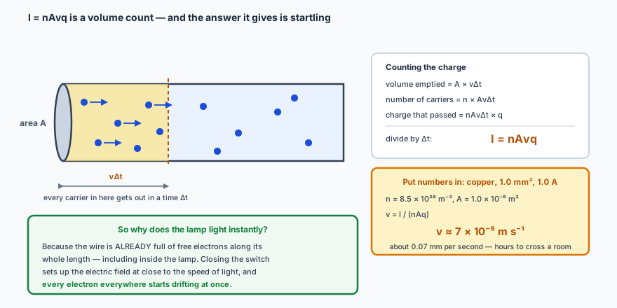
Consider a conductor of cross-sectional area \(A\) containing \(n\) free charge carriers per unit volume, each of charge \(q\), drifting along at average speed \(v\):
\[ I = nAvq \]
The derivation is a volume count. The answer it gives is startling — and it is the reason the next paragraph exists.
For a typical copper wire the drift speed works out at well under a millimetre per second: a given electron would take hours to travel the length of a room. Yet the lamp lights instantly. There is no contradiction — the wire is already full of free electrons everywhere along its length, and the electric field that sets them all moving is established at close to the speed of light. Nothing has to travel from the switch to the lamp; everything is already in place, waiting to be pushed.
🔋Potential difference, emf, and resistance
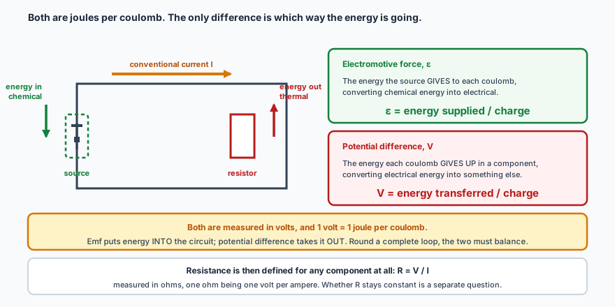
Both of the first two are energy per unit charge, and the distinction between them is a favourite exam question.
Same unit, same definition, opposite direction of conversion. Emf puts energy in; potential difference takes it out.
p.d.\( V = \dfrac{\text{energy transferred}}{\text{charge}} \)
resistance\( R = \dfrac{V}{I} \)
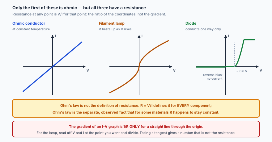
Resistance is defined by that last equation for every component, ohmic or not. What varies is whether \(R\) is constant.
Only the first is ohmic. On any \(I\)–\(V\) graph, resistance at a point is \(V/I\) for that point — not the gradient, unless the line happens to pass through the origin.
The gradient of an \(I\)–\(V\) graph is not \(1/R\) unless the graph is a straight line through the origin. For a filament lamp, the resistance at any point is \(V/I\) at that point — the ratio of the coordinates, which you can get by drawing a line from the origin. Taking the tangent instead gives a different number that is not the resistance. This costs marks every year.
Ohm’s law is not the definition of resistance; it is the observed fact that for some materials, at constant temperature, \(V\) is proportional to \(I\). A filament lamp disobeys it, and does not thereby stop having a resistance.
📏Resistivity: resistance from the material and the shape
The resistance of a wire depends on what it is made of and on its dimensions:
\[ R = \frac{\rho L}{A} \]
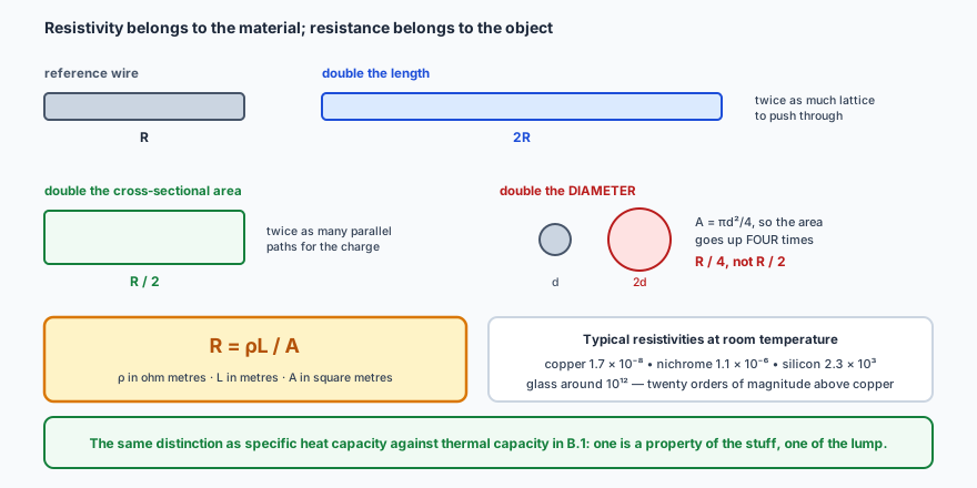
\( \rho \) belongs to the material; \(R\) belongs to the object. It is the same distinction as specific heat capacity against thermal capacity in B.1.
Watch the area term when a question gives you a diameter: \( A = \pi r^{2} = \pi d^{2}/4 \), so doubling the diameter quarters the resistance, not halves it.
✏️Worked example 1 — charge, electrons, and a wire’s resistance
(a) A current of 2.0 A flows for 5.0 minutes. Find the charge transferred and the number of electrons involved.
(b) Find the resistance of a copper wire of length 2.0 m and diameter 0.50 mm. Take \( \rho = 1.7\times10^{-8} \) Ω m.
Both answers pass a plausibility test. \( 10^{21} \) electrons is an enormous number, which it should be — each one carries only \( 10^{-19} \) C. And a fifth of an ohm for two metres of thin copper is about right: connecting wires are supposed to have negligible resistance compared with the components they connect. If (b) had come out in the hundreds of ohms, the likely error is using the diameter as the radius, which would be four times too small an area.
🔌Power in a circuit
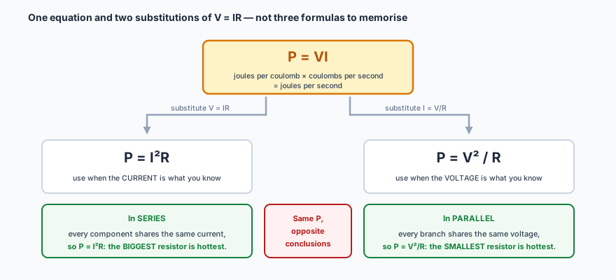
Power is energy per unit time, and in a circuit that gives one equation with two useful rearrangements:
\( P = VI \)
\( P = I^{2}R \)
\( P = \dfrac{V^{2}}{R} \)
Not three formulas — one formula and two substitutions of \(V = IR\). Choosing the right one is just choosing the quantity you already know.
🔗Series and parallel
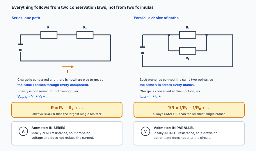
Everything follows from two conservation laws: charge is conserved at a junction, and energy is conserved round a loop. The formulas are consequences, not extra facts.
Two sanity checks worth applying to every answer: a series combination is always larger than the biggest resistor in it, and a parallel combination is always smaller than the smallest. If your parallel answer is bigger than one of the branches, you have forgotten to invert at the end.
Ideal meters are defined by not disturbing what they measure. An ammeter goes in series and ideally has zero resistance, so it drops no voltage. A voltmeter goes in parallel and ideally has infinite resistance, so it draws no current.
🔋Internal resistance: why a battery’s voltage sags
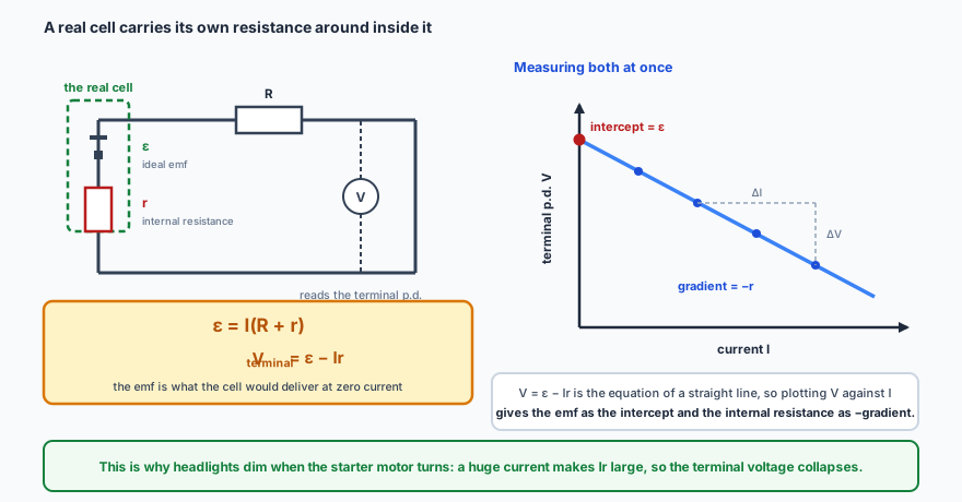
A real cell is not just a source of emf. The chemicals inside it have resistance too, and that internal resistance \(r\) is in series with everything else in the circuit:
The emf is what the cell would deliver at zero current. Draw any current and some of it is spent inside the cell itself — which is why a car’s headlights dim when the starter motor turns.
✏️Worked example 2 — a cell under load
A cell of emf 6.0 V and internal resistance 0.50 Ω is connected to a 2.5 Ω resistor. Find the current, the terminal potential difference, the power delivered to the resistor and the power wasted inside the cell.
Check the total. The cell supplies \( \varepsilon I = 6.0\times2.0 = 12 \) W, and \( 10 + 2.0 = 12 \) W is accounted for. Note that a sixth of the energy is being wasted heating the cell itself, and that the terminal voltage has sagged from 6.0 V to 5.0 V. Draw a bigger current and it sags further — which is exactly what a voltmeter shows when a battery is described as “flat”: the emf is often nearly unchanged, but \(r\) has risen.
⚖️The potential divider
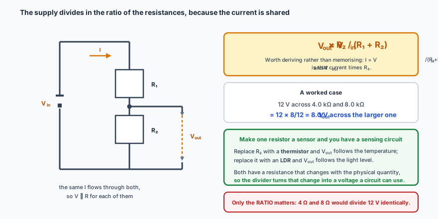
Two resistors in series across a supply split the voltage between them in the ratio of their resistances, because the same current passes through both:
The formula is worth deriving rather than memorising: the current is \( V_{\text{in}}/(R_1+R_2) \), and \( V_{\text{out}} \) is that current times \(R_2\).
✏️Worked example 3 — dividing a supply
A 12 V supply is connected across a 4.0 kΩ resistor in series with an 8.0 kΩ resistor. Find the potential difference across the 8.0 kΩ resistor, and the power dissipated in it.
The bigger resistor gets the bigger share. Two thirds of the resistance, two thirds of the voltage — and the ratio is all that matters, so 4 Ω and 8 Ω would divide it identically. Note also that the kilohms had to become ohms before the power calculation: using 8.0 rather than 8000 would have given 8 W, a thousand times too large.
🔭See it happen
PhET, Circuit Construction Kit: DC. Build the circuits above, switch on the
electron view, and watch how slowly the charges actually crawl while the bulb lights at once.
Then give the battery some internal resistance and watch the terminal voltage sag as you lower
the external resistance — the whole of worked example 2, live.
📝Practise
Work through these, then reveal the answer. Each question targets a different objective from the list above.
1. A charge of 45 C passes a point in 90 s. Find the current, and the number of electrons involved.
\( I = \Delta q/\Delta t = 45/90 = 0.50 \) A. Number of electrons \( N = Q/e = 45/(1.60\times10^{-19}) = 2.8\times10^{20} \).
2. Explain why a lamp lights almost instantly even though the drift speed of the electrons is less than a millimetre per second.
The wire already contains free electrons along its entire length — nothing has to travel from the switch to the lamp. Closing the switch establishes an electric field throughout the circuit at close to the speed of light, and every electron everywhere begins to drift almost at once, including the ones already inside the lamp. The drift speed governs how far an individual electron gets, not how quickly the current starts.
3. A wire of resistance 12 Ω is stretched uniformly to twice its original length. Find its new resistance.
Stretching does not change the volume, so doubling the length halves the cross-sectional area. In \( R = \rho L/A \), the numerator doubles and the denominator halves, so the resistance goes up by a factor of 4: \( R = 48\ \Omega \). Answering 24 Ω means the area was forgotten.
4. Sketch the \(I\)–\(V\) characteristic of a filament lamp and explain its shape.
The curve starts straight through the origin, then bends over towards the voltage axis: equal increases in \(V\) produce smaller and smaller increases in \(I\). As the current rises the filament gets hotter, so the lattice ions vibrate with greater amplitude, the free electrons collide with them more often, and the resistance rises. Since \( R = V/I \) increases with \(V\), the graph must flatten.
5. Resistors of 6.0 Ω and 3.0 Ω are connected in parallel, and that combination is in series with a 4.0 Ω resistor across a 12 V supply of negligible internal resistance. Find the total resistance and the current from the supply.
Parallel first: \( 1/R = 1/6.0 + 1/3.0 = 0.5 \), so \( R = 2.0\ \Omega \) — and note it is smaller than either branch, as it must be. Total \( = 2.0 + 4.0 = 6.0\ \Omega \). Current \( I = V/R = 12/6.0 = 2.0 \) A.
6. State where an ammeter and a voltmeter are connected, and what resistance each ideally has.
An ammeter is connected in series with the component whose current is being measured, and ideally has zero resistance so that it drops no potential difference and does not reduce the current. A voltmeter is connected in parallel with the component, and ideally has infinite resistance so that it draws no current and does not alter the circuit it is measuring.
7. A cell of emf 1.5 V has an internal resistance of 0.80 Ω. Find the terminal potential difference when it drives a current of 0.50 A.
\( V = \varepsilon - Ir = 1.5 - 0.50\times0.80 = 1.5 - 0.40 = 1.1 \) V. The missing 0.40 V is dissipated inside the cell itself.
8. A student plots terminal potential difference against current for a cell and obtains a straight line with intercept 4.5 V and gradient −1.5 V A\(^{-1}\). State the emf and the internal resistance.
Rearranged, \( V = \varepsilon - Ir \) is the equation of a straight line with \(V\) on the \(y\)-axis and \(I\) on the \(x\)-axis. The intercept is the emf, so \( \varepsilon = 4.5 \) V, and the gradient is \( -r \), so \( r = 1.5\ \Omega \). The intercept is the emf because it is the terminal voltage at zero current, when nothing is lost inside the cell.
9. A 24 V supply is connected across a 3.0 kΩ resistor in series with a 9.0 kΩ resistor. Find the output voltage taken across the 3.0 kΩ resistor.
\( V_{\text{out}} = 24 \times \dfrac{3.0}{3.0 + 9.0} = 24 \times 0.25 = 6.0 \) V. The smaller resistor takes the smaller share — a quarter of the resistance, a quarter of the voltage.
10. A 60 W lamp and a 100 W lamp are both designed for 240 V. Which has the greater resistance, and what current does each draw?
From \( P = V^{2}/R \), \( R = V^{2}/P \), so a lower power at the same voltage means a higher resistance. The 60 W lamp: \( R = 240^{2}/60 = 960\ \Omega \), drawing \( I = P/V = 0.25 \) A. The 100 W lamp: \( R = 240^{2}/100 = 576\ \Omega \), drawing 0.42 A. The brighter lamp has the lower resistance, which surprises most people the first time.
🔗Go deeper — other people’s work
These are external resources, not mine. If one stops working, tell me and
everything above it on this page still stands.
HyperPhysics — DC circuits and resistivity
The Physics Hypertextbook — electric current and resistance