Theme C · Wave behaviour · SL and HL, with additional HL material marked
Everything on this page follows from one sentence in C.2: a ray is always at right angles to its wavefront. Slow one edge of a wavefront down and the whole front swings round — that is refraction. Chop a wavefront off with an obstacle and the ends spread — that is diffraction. Overlap two wavefronts and add the displacements — that is interference. Three phenomena, one idea.
🎯What you need to be able to do
Apply the law of reflection, and distinguish specular from diffuse reflection.
Use Snell’s law and refractive index, in the forms \( n = \dfrac{\sin i}{\sin r} \), \( \dfrac{n_1}{n_2} = \dfrac{v_2}{v_1} \) and \( n_1\sin\theta_1 = n_2\sin\theta_2 \).
Explain refraction using wavefronts, and say which of speed, wavelength and frequency changes.
Find a critical angle and describe total internal reflection and its uses.
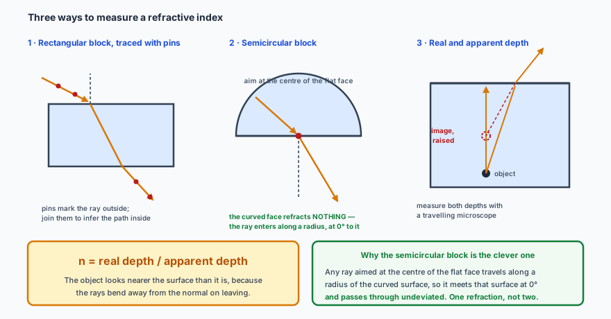
Describe methods of measuring a refractive index experimentally.
Describe diffraction and state the condition under which it is noticeable.
Apply the principle of superposition, and use path difference to predict constructive and destructive interference.
Describe Young’s double-slit experiment and use \( s = \dfrac{\lambda D}{d} \).
HL Use \( \theta = \dfrac{\lambda}{b} \) for the first minimum of single-slit diffraction and sketch the intensity pattern.
HL Explain how single-slit diffraction modulates the double-slit pattern.
HL Use \( n\lambda = d\sin\theta \) for a diffraction grating, and explain why more slits give sharper maxima.
🪞Reflection
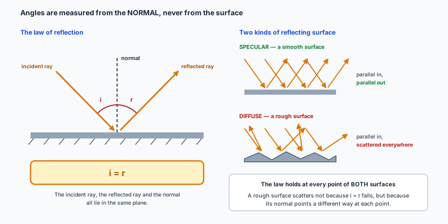
When a wave meets a boundary between two media it is in general partly reflected and partly transmitted. Angles are always measured from the normal — the construction line drawn at right angles to the surface — never from the surface itself.
The law holds at every point of both surfaces. A rough surface scatters not because the law fails but because its normal changes direction from point to point.
\[ i = r \]
Diffuse reflection is why you can see this page at all: almost nothing around you emits its own light, so you see objects by the light they scatter in all directions. Your brain then locates them by assuming the rays travelled in straight lines.
🔄Refraction and Snell’s law
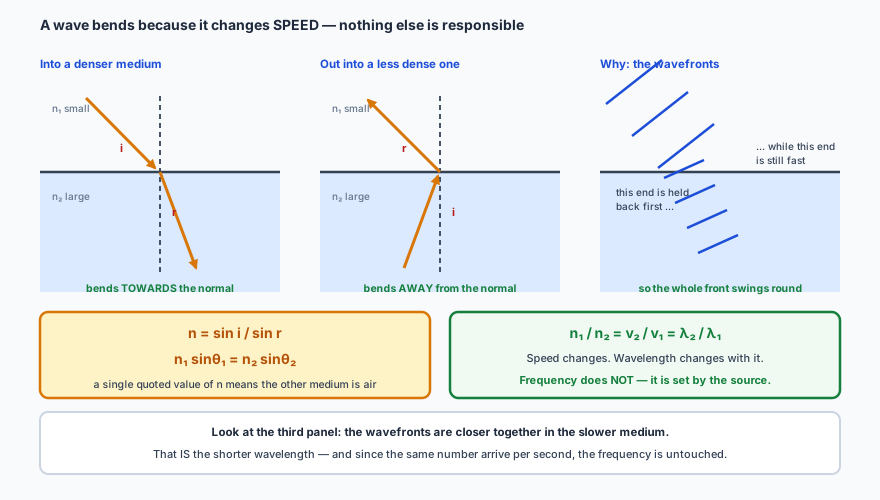
A wave crossing into a new medium changes direction, and the reason is that it changes speed. Nothing else about it is responsible.
The wavefront picture is the explanation; the ray picture is the bookkeeping. One end of the front is held back, so the front pivots — exactly like a marching band wheeling round a corner.
Going into an optically denser medium (larger \(n\), slower wave), the ray bends towards the normal; coming out into a less dense one it bends away. If a refractive index is quoted as a single number, the other medium is air, for which \( n = 1.0 \).
Three quantities cross the boundary; only two of them change. The speed changes, because the medium changed. The wavelength changes with it, in the same ratio. The frequency does not change — it is fixed by the source, and a boundary cannot create or destroy oscillations. Since \( v = f\lambda \) with \(f\) constant, \( \lambda \propto v \), which is why the wavefronts in the figure crowd together in the slower medium.
✏️Worked example 1 — Snell’s law, once and then twice
(a) Light in air strikes a glass block of refractive index 1.34 at an angle of incidence of 40°. Find the angle of refraction. (b) A ray in air enters a glass sheet (\( n = 1.6 \)) at 40° and passes out of the far side into water (\( n = 1.3 \)). Find the final angle in the water.
\[ \sin r = \frac{\sin 40^\circ}{1.34} = \frac{0.6428}{1.34} = 0.4797 \quad\Rightarrow\quad r = 28.7^\circ \]
(b) Do the two boundaries in turn. Air to glass first:
The glass has done nothing to the final direction. Check it: \( \sin 40^\circ / \sin 29.6^\circ = 1.30 \), which is exactly the refractive index of water. The intermediate layer shifts the ray sideways but the overall bend depends only on the first and last media — the \( n_{\text{glass}} \) cancels straight out of \( n_1\sin\theta_1 = n_2\sin\theta_2 = n_3\sin\theta_3 \). Spotting that saves a whole line of algebra.
🔒Total internal reflection
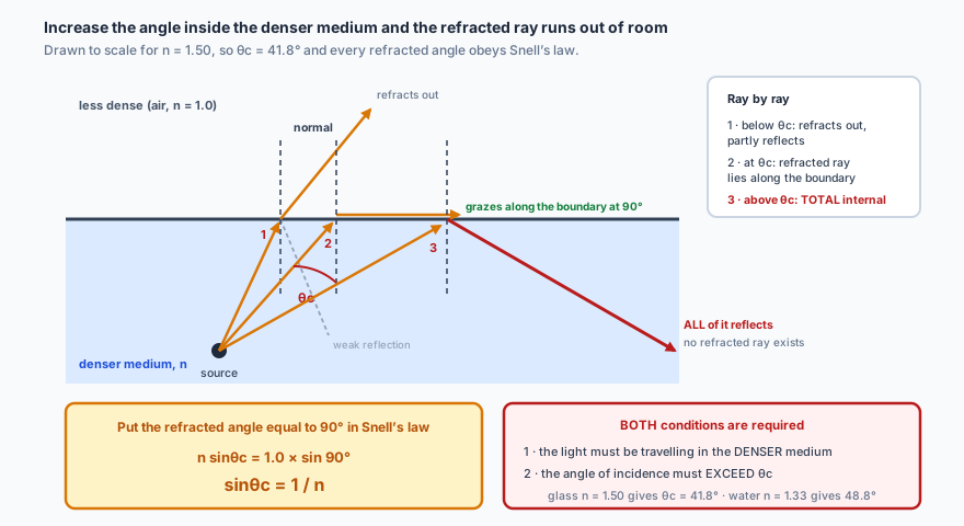
Send a ray the other way — from the denser medium towards the less dense one — and it bends away from the normal. Increase the angle of incidence and the refracted ray swings closer and closer to the boundary itself. At some angle it lies flat along the boundary, and beyond that there is nowhere for it to go.
Ray 2 defines the critical angle: the refracted ray at exactly 90°. Past it, refraction has no solution — \( \sin\theta \) would have to exceed 1 — so all the light reflects.
Two conditions, both required: the light must be travelling in the denser medium, and the angle of incidence must exceed the critical angle.
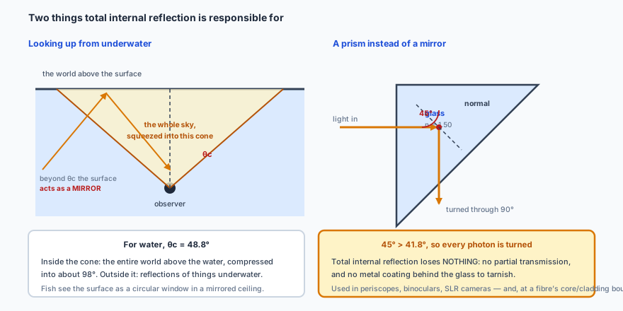
A prism beats a mirror because total internal reflection loses nothing: there is no partial transmission and no tarnished silvering behind the glass.
✏️Worked example 2 — a critical angle, and why 45° prisms work
Find the critical angle for a glass–air boundary where the glass has \( n = 1.50 \), and explain why a 45° prism totally internally reflects light that strikes its hypotenuse.
Light entering the short face of a right-angled isosceles prism travels straight to the hypotenuse and meets it at 45°. Since \( 45^\circ > 41.8^\circ \), the condition for total internal reflection is met and every photon turns through 90°.
The margin is only about three degrees, and that matters. A glass with \( n = 1.40 \) would have \( \theta_{\text{c}} = 45.6^\circ \), and the same prism would leak light instead of reflecting it. It is also why optical fibres are made with a core of higher index than the cladding: the critical angle at that internal boundary is what keeps the light trapped over kilometres.
🔬Measuring a refractive index
The semicircular block is the clever one: aim at the centre and the curved face refracts nothing, because the ray enters along a radius and so meets that surface at 0°.
\[ n = \frac{\text{real depth}}{\text{apparent depth}} \]
🌊Diffraction
Waves passing through a gap, or round the edge of an obstacle, spread out into the region that ray optics says should be in shadow.
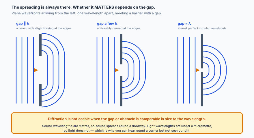
The spreading is always there. Whether it matters depends entirely on how the gap compares with the wavelength.
Diffraction is noticeable when the aperture or obstacle is comparable in size to the wavelength. That single sentence explains a great deal:
You can hear someone round a corner but not see them: sound wavelengths are metres, light wavelengths are fractions of a micrometre, and a doorway is about a metre across.
No optical microscope can ever resolve an atom, because atoms are far smaller than the wavelength of visible light. Electron microscopes work because electrons have a much shorter effective wavelength.
A radio telescope’s dish size sets the finest detail it can distinguish, which is why several are linked into arrays.
➕Superposition and interference
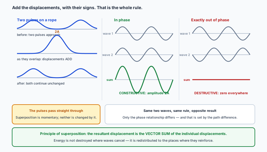
When two waves of the same type meet, the principle of superposition says the resulting displacement at any point is the vector sum of the displacements each wave would produce alone. Nothing more complicated is happening: the waves pass through each other and carry on unchanged.
Add the displacements, with their signs. Everything about interference — every bright fringe and every quiet patch — is that one instruction applied point by point.
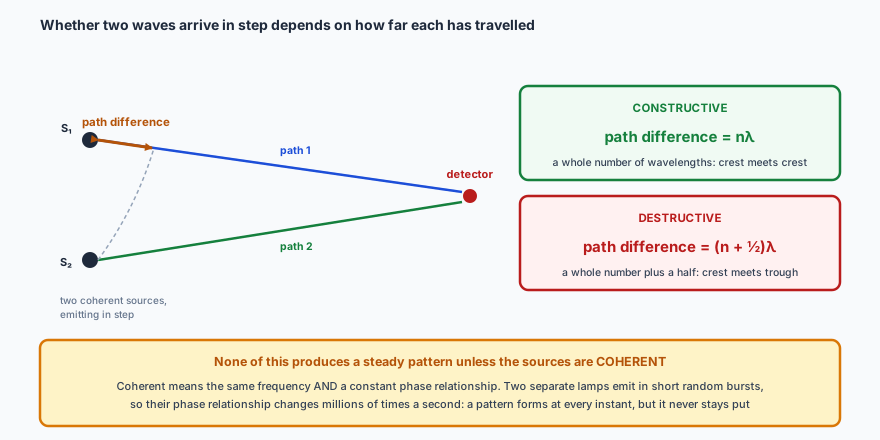
Whether two waves arrive in step depends on how far each has travelled. The path difference is the extra distance one has covered:
Path difference is the whole story — but only if the sources are coherent. Two independent lamps have a phase relationship that changes millions of times a second, so their pattern averages away to nothing.
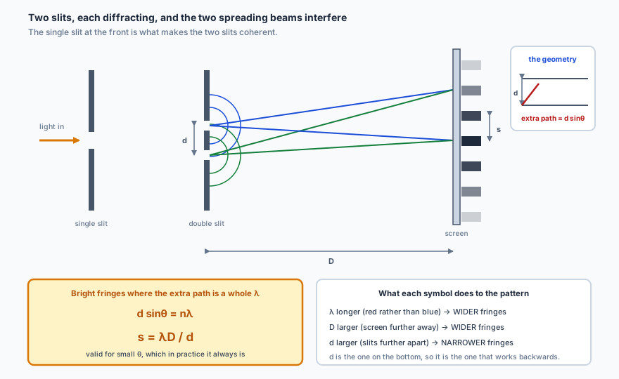
Light from a single source is passed through two narrow, closely spaced slits. Each slit diffracts, the two spreading beams overlap, and where they overlap they interfere — producing a row of evenly spaced bright and dark fringes on a screen.
The single slit at the front is what makes the two slits coherent — they are both lit by the same wavefront, so their phase relationship never changes. A laser makes it unnecessary.
The small-angle approximation is doing real work here: \( s = \lambda D/d \) holds only when \( \theta \) is small, which in practice it always is, since \(d\) is under a millimetre and \(D\) is metres.
✏️Worked example 3 — fringe spacing
Laser light of wavelength 450 nm is shone on two slits 0.10 mm apart. How far apart are the fringes on a screen 5.0 m away?
Every length had to be in metres, and two of them were not. 450 nm became \( 4.5\times10^{-7} \) m and 0.10 mm became \( 1.0\times10^{-4} \) m. A 2.3 cm fringe spacing is comfortably measurable with a ruler, which is the point of putting the screen 5 m away: halve \(D\) and the fringes halve too. Note also that a longer wavelength gives wider fringes — red fringes are more spread out than blue ones.
📐HL The mathematics of single-slit diffraction
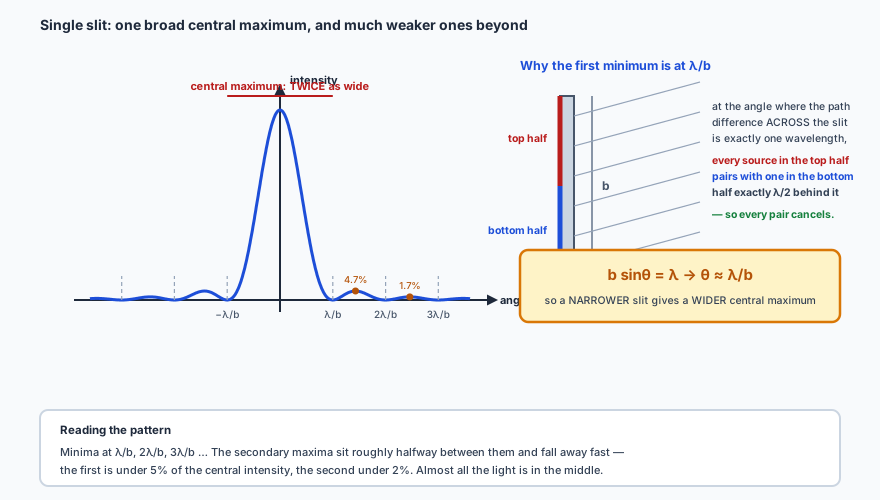
A single slit of width \(b\) produces its own pattern: a broad, bright central maximum with much weaker maxima either side, separated by minima.
The pairing argument is the whole derivation: at \( b\sin\theta = \lambda \), every point in the top half cancels its partner in the bottom half.
Note what that says: a narrower slit gives a wider central maximum. The central maximum is also twice as wide as each of the others, running from \( -\lambda/b \) to \( +\lambda/b \).
✏️Worked example 4 —HL a wavelength from a single slit
Laser light passes through a single slit of width 0.080 mm and is projected onto a screen 2.0 m away. The central maximum is measured to be 3.0 cm wide. Find the wavelength.
The central maximum runs from the first minimum on one side to the first minimum on the other, so its half-width corresponds to \( \theta \):
600 nm is orange-red, which a cheap laser pointer would be. That plausibility check is worth doing every time: any answer outside roughly 400–700 nm for visible light means an arithmetic slip. The commonest one here is forgetting to halve the measured width — using 3.0 cm instead of 1.5 cm would have given 1200 nm, well into the infrared and therefore invisible.
🔭HL Real double slits have width
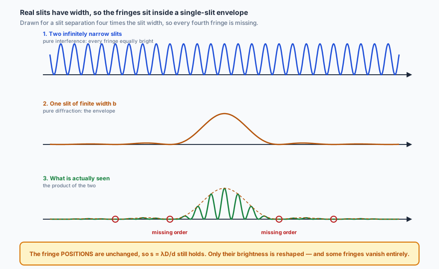
The tidy row of equal-brightness fringes above assumed the slits were infinitely narrow. Real slits have a width \(b\), so each one produces its own single-slit pattern — and the two effects multiply.
The fringe positions are unchanged, so \( s = \lambda D/d \) still holds. What changes is their brightness — and a fringe landing on a diffraction minimum disappears entirely.
📈HL The diffraction grating
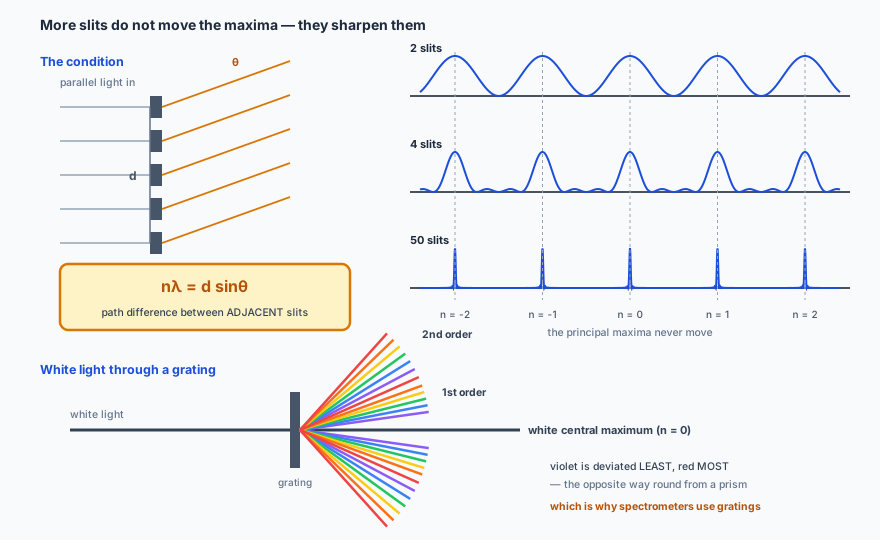
A diffraction grating is a very large number of parallel slits at a constant spacing \(d\). Adding more slits does not move the maxima — the condition for constructive interference between adjacent slits is unchanged — but it makes them dramatically sharper.
Why sharper? With only two slits, an angle slightly off a maximum still gives nearly-in-phase light. With fifty, a slight offset means some distant slit is exactly out of phase with yours, and the sum collapses.
\[ n\lambda = d\sin\theta \]
Because \( \theta \) depends on \( \lambda \), a grating separates colours: white light gives a white central maximum (all wavelengths have \( \theta = 0 \) for \( n = 0 \)) flanked by complete spectra, with violet deviated least and red most. That is the reverse of a prism, and it is why gratings, not prisms, are used in spectrometers for accurate wavelength measurement.
✏️Worked example 5 —HL a grating
A diffraction grating has 20 lines per millimetre and is illuminated normally with light of wavelength 500 nm. Find the angle of the first-order maximum and the angular separation between the first and second orders.
The slit spacing is the reciprocal of the number of lines per metre:
\[ d = \frac{1}{20\times10^{3}\ \text{m}^{-1}} = 5.0\times10^{-5}\ \text{m} \]
The two gaps came out equal, and that is a small-angle coincidence, not a rule. For small \( \theta \), \( \sin\theta \approx \theta \), so the orders are evenly spaced. Push to high orders and they crowd together: at \( n = 100 \), \( \sin\theta = 1.0 \) and \( \theta = 90^\circ \), which is the absolute limit — no order can exist for which \( n\lambda > d \). Watch the “lines per mm” conversion too: 20 lines per mm is 20 000 lines per metre, so \(d\) is \( 5.0\times10^{-5} \) m, not \( 5.0\times10^{-2} \).
🔭See it happen
PhET, Bending Light for refraction and the critical angle — drag the angle past
\( \theta_{\text{c}} \) and watch the refracted ray vanish. Then PhET, Wave Interference,
which lets you narrow a single slit until the diffraction is obvious, then open a second slit and
watch the fringes appear inside the envelope.
📝Practise
Work through these, then reveal the answer. Each question targets a different objective from the list above.
1. Light travels from air into a medium of refractive index 1.5 at an angle of incidence of 30°. Find the angle of refraction, and state what happens to the speed, wavelength and frequency.
\( \sin r = \sin 30^\circ/1.5 = 0.333 \), so \( r = 19.5^\circ \) — bent towards the normal, as expected on entering a denser medium. The speed falls by a factor of 1.5, and the wavelength falls in the same ratio. The frequency is unchanged, because it is determined by the source.
2. Calculate the wavelength of electromagnetic radiation of frequency \( 5.0\times10^{14} \) Hz (a) in air and (b) in glass of refractive index 1.5.
(a) \( \lambda = c/f = 3.0\times10^{8}/5.0\times10^{14} = 6.0\times10^{-7} \) m. (b) In glass the speed is \( c/n = 2.0\times10^{8} \) m s\(^{-1}\) and the frequency is unchanged, so \( \lambda = 2.0\times10^{8}/5.0\times10^{14} = 4.0\times10^{-7} \) m. Equivalently, just divide the air wavelength by \(n\).
3. Find the critical angle for water of refractive index 1.33, and explain what an observer underwater sees when looking up at more than that angle from the vertical.
\( \sin\theta_{\text{c}} = 1/1.33 = 0.752 \), so \( \theta_{\text{c}} = 48.8^\circ \). Looking up at less than 48.8° from the vertical, the observer sees the whole world above the surface, compressed into that cone. Beyond it, no light can get in from above, so the surface acts as a mirror and they see reflections of objects that are under the water.
4. State the two conditions necessary for total internal reflection.
The light must be travelling in the optically denser medium (moving towards a medium of lower refractive index), and the angle of incidence at the boundary must be greater than the critical angle. If either fails, some light refracts out.
5. Explain why you can hear a person talking round a corner but cannot see them.
Both sound and light diffract at the corner, but diffraction is only significant when the obstacle or gap is comparable in size to the wavelength. Audible sound has wavelengths of roughly 0.02–20 m, comparable with a doorway or a corner, so it spreads round appreciably. Visible light has wavelengths of about \( 5\times10^{-7} \) m, millions of times smaller than the corner, so its spreading is far too small to notice and it travels effectively in straight lines.
6. Two coherent sources emit waves of wavelength 3.0 cm. At a point, the path difference is 7.5 cm. Is the interference constructive or destructive?
\( 7.5/3.0 = 2.5 \) wavelengths, which is \( \left(2 + \frac{1}{2}\right)\lambda \) — a whole number plus a half. So the waves arrive exactly out of phase and the interference is destructive.
7. State what is meant by coherent sources, and explain why two separate lamps do not produce an observable interference pattern.
Coherent sources have the same frequency and a constant phase relationship between them. Two separate lamps emit light in short, random bursts, so their phase relationship changes millions of times a second. An interference pattern does form at every instant, but it shifts position far faster than the eye or any detector can follow, so it averages out to uniform illumination.
8. In a double-slit experiment the fringe spacing is 1.8 mm. What happens to it if (a) the screen is moved twice as far away, (b) the slit separation is doubled, (c) the light is changed from blue to red?
From \( s = \lambda D/d \): (a) doubling \(D\) doubles \(s\) to 3.6 mm; (b) doubling \(d\) halves \(s\) to 0.9 mm; (c) red light has a longer wavelength than blue, so the fringes get wider. Fringe spacing is proportional to \( \lambda \) and to \(D\), and inversely proportional to \(d\).
9. HL Light of wavelength 600 nm passes through a slit of width 0.12 mm. Find the angular width of the central maximum.
The first minimum is at \( \theta = \lambda/b = 6.0\times10^{-7}/1.2\times10^{-4} = 5.0\times10^{-3} \) rad. The central maximum runs from \( -\theta \) to \( +\theta \), so its full angular width is \( 1.0\times10^{-2} \) rad, about 0.57°. Remember that the central maximum is twice as wide as the subsequent ones.
10. HL Red light of wavelength 700 nm is incident normally on a grating, and the first-order maximum appears at effectively 90°. Estimate the grating spacing, and find where the first-order maximum for 400 nm blue light would appear.
For the first order at 90°, \( d\sin 90^\circ = 1\times\lambda \), so \( d = 7.0\times10^{-7} \) m — about 1400 lines per millimetre. For the blue light, \( \sin\theta = 400/700 = 0.571 \), giving \( \theta = 34.8^\circ \). So the entire first-order visible spectrum is spread between 34.8° and 90°, with violet closest to the centre — an enormous dispersion, which is exactly what a grating is for.
🔗Go deeper — other people’s work
These are external resources, not mine. If one stops working, tell me and
everything above it on this page still stands.
HyperPhysics — refraction, interference and diffraction
The Physics Hypertextbook — refraction and diffraction