Everything on this page comes from one sentence: a changing magnetic flux drives a
current. The rest is working out how fast it is changing, and which way the current goes.
🎯What you need to be able to do
Calculate magnetic flux \( \Phi = BA\cos\theta \) and flux linkage \( N\Phi \), measuring \(\theta\) from the normal.
Apply Faraday’s law to find an induced emf, and name the three things that can change the flux.
Apply Lenz’s law to find the direction of an induced current, and argue why it must follow from conservation of energy.
Use \( \varepsilon = BvL \), and \( \varepsilon = BvLN \) for a coil, and explain the opposing force that appears once current flows.
Use Fleming’s right-hand rule to find the direction of an induced current.
Explain the AC generator, use \( \varepsilon = NBA\omega\sin\omega t \), and sketch how the output changes with \(B\) and \(\omega\).
Use rms values for alternating current and voltage, and relate average power to peak power.
Explain self-induction and back emf, and why a current takes time to build up in a coil.
Explain eddy currents, and the everyday effects they produce.
🧭Flux, and the angle everyone measures from the wrong place
\[ \Phi = BA\cos\theta \]
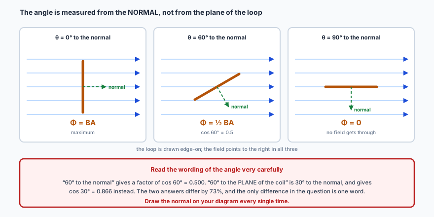
Flux measures how much field passes through a loop. The angle \(\theta\) is between the field and
the normal to the area — the line sticking out perpendicular to the loop
— and not the plane of the loop. Measure it from the plane instead and every cosine in
your working becomes a sine.
Flux is greatest when the field is perpendicular to the loop’s plane and zero when the field lies in that plane — which is the opposite of what “90 degrees” makes most people expect. Sketch the normal every time.
Flux linkage is \( N\Phi \) for a coil of \(N\) turns, since each turn links the
same flux. Both are measured in webers.
✏️Worked example 1 — flux and flux linkage
A coil of 200 turns and area \( 4.0\times10^{-3} \) m\(^{2}\) sits in a uniform field of 0.25 T.
Find the flux and the flux linkage when the field is at 60° to the normal, and when it is
along the normal.
At 60° to the normal:
\( \Phi = BA\cos\theta = 0.25 \times 4.0\times10^{-3} \times \cos 60^\circ = 5.0\times10^{-4} \) Wb,
and \( N\Phi = 200 \times 5.0\times10^{-4} = 0.10 \) Wb.
Along the normal (\(\theta = 0\)):
\( \Phi = 1.0\times10^{-3} \) Wb and \( N\Phi = 0.20 \) Wb — the maximum.
\(\cos 60^\circ = 0.5\), so the flux halves. If a question says the field is at
60° to the plane of the coil instead, that is 30° to the normal and the factor is
\(\cos 30^\circ = 0.866\). Read that phrase carefully — it is the single most reliable way
to lose marks on this topic, and the two answers differ by 73%.
⚡Faraday’s law: only change counts
\[ \varepsilon = -N\frac{\Delta\Phi}{\Delta t} \]
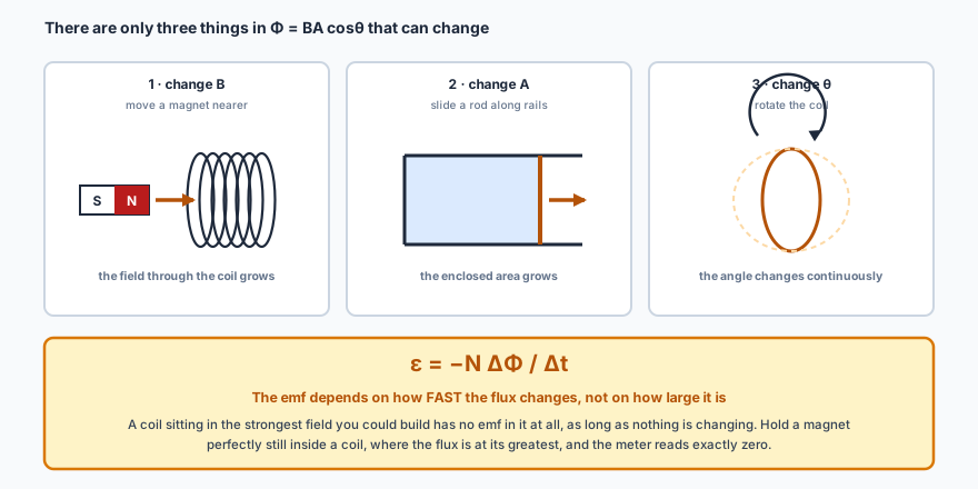
The induced emf depends on the rate of change of flux linkage, not on the flux
itself. A coil sitting in the strongest field you can build has no emf in it at all while nothing
changes. Something must vary, and there are only three candidates.
Change \(B\), change \(A\), or change \(\theta\) — there is nothing else in \( \Phi = BA\cos\theta \) to change. Every induction question in the syllabus is one of these three, and identifying which is usually the first mark.
✏️Worked example 2 — rotating a coil
The same coil (200 turns, \( 4.0\times10^{-3} \) m\(^{2}\), 0.25 T) is turned from
“field along the normal” to “field in the plane of the coil” in 0.050 s.
Find the average emf induced.
“Average” is doing real work in that question. Faraday’s law
with \(\Delta\) gives the average emf over the interval; the instantaneous emf varies throughout
the turn and is largest when the coil sweeps through the position where the field lies in its
plane. Note also that turning it faster gives a bigger emf from the same magnet — the flux
change is identical, but it happens in less time.
🚫Lenz’s law: the induced current always fights you
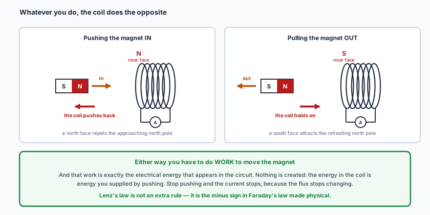
That minus sign in Faraday’s law is Lenz’s law: the induced current flows in
whatever direction opposes the change that produced it.
Push it in and the coil pushes back; pull it out and the coil hangs on. Either way you have to work to move the magnet, and that work is precisely the electrical energy that appears.
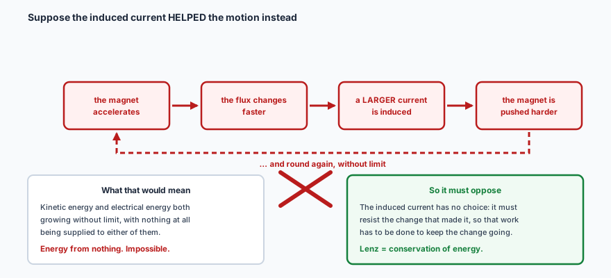
Why it has to be that way is a standard extended-response question, and the
argument is short. Suppose the induced current helped the motion instead.
A perpetual motion machine, and a rapidly accelerating one. Lenz’s law is not an extra rule bolted on to Faraday’s — it is conservation of energy, written in the language of induction.
📏A rod moving through a field
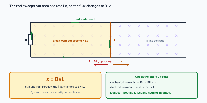
The simplest case of all. A rod of length \(L\) moving at speed \(v\) perpendicular to a field
\(B\) sweeps out area at a rate \(Lv\), so the flux changes at a rate \(BLv\):
\[ \varepsilon = BvL \]
Once the circuit is complete a current flows, and that current in that field puts a force \(BIL\) on the rod — backwards. Lenz again. Push harder and you get more power out, which is exactly the bargain a generator makes.
Which way does the induced current go? This is what
Fleming’s right-hand rule is for, and it
is the rule to reach for whenever the motion is what you are given: first finger along the
Field, thuMb along the Motion, and the
seCond finger then points along the induced Current. Use the left
hand here by mistake and you will get a current in exactly the wrong direction.
Why an emf appears at all is worth one line of mechanism. The rod is full of free electrons, and
each of them is moving with the rod through the field, so each feels a magnetic force \(qvB\) that
pushes it towards one end. Charge piles up there until the electric field it creates pushes back just
as hard, and at that point the potential difference across the rod is steady. Setting the two forces
equal for an electron in the middle gives \( qvB = qE = qV/L \), so \( V = BvL \) — the same
answer the flux argument gave, from the other direction.
For a coil of \(N\) turns whose side is in the field, each turn generates \(BvL\) and they add
in series:
\[ \varepsilon = BvLN \]
with one condition worth noticing: only the part of the coil inside the field generates
anything. If the whole coil sits inside a uniform field, both sides generate equal emfs that oppose
each other round the loop, and no current flows at all.
✏️Worked example 3 — the emf across an aircraft
An aircraft with a wingspan of 30 m flies at 200 m s\(^{-1}\). The vertical component of the
Earth’s magnetic field is \( 5.0\times10^{-5} \) T. Estimate the potential difference
between its wingtips.
Why the vertical component, and not the whole field? Because \(B\), \(v\) and
\(L\) must be mutually perpendicular. The wings are horizontal and across the motion, so the only
part of the field that counts is the part perpendicular to both — the vertical component.
Using the full field strength is the standard error here. And 0.30 V is real but useless: it
drives no current, because there is no circuit to complete through the air.
🔄The AC generator
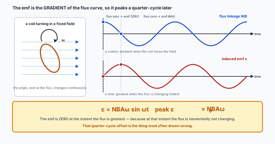
Rotate a coil steadily in a uniform field and the angle changes continuously, so
\( \Phi = BA\cos\omega t \) and the flux linkage varies sinusoidally. Faraday’s law turns that
cosine into a sine:
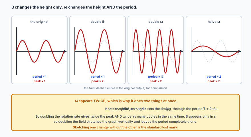
The emf is zero when the flux is greatest and greatest when the flux is zero — because it is the gradient of the flux curve, not the flux. That quarter-cycle offset is the thing most often drawn wrong.Changing \(B\) changes only the height. Changing \(\omega\) changes the height and the period together, because \(\omega\) appears in \( \varepsilon_0 = NBA\omega \) as well as in the timing. Sketching one without the other is the standard lost mark.
✏️Worked example 4 — a generator’s peak output
A coil of 50 turns and area \( 2.0\times10^{-2} \) m\(^{2}\) rotates at 50 revolutions per second
in a field of 0.30 T. Find the peak emf.
Convert to angular velocity first:
\( \omega = 2\pi f = 2\pi \times 50 = 314 \) rad s\(^{-1}\).
Revolutions per second is not \(\omega\). Forgetting the \(2\pi\) gives 15 V
instead of 94 V — a factor of \(2\pi\) out, and the most common single error in generator
questions. As a check, doubling the rotation rate would double this to 188 V and halve
the period; changing the field would move only the height.
🔋rms values: what “230 volts” actually means
The generator’s output swings from \( +\varepsilon_0 \) to \( -\varepsilon_0 \) and
averages zero, so quoting an average voltage would be useless. What matters is the
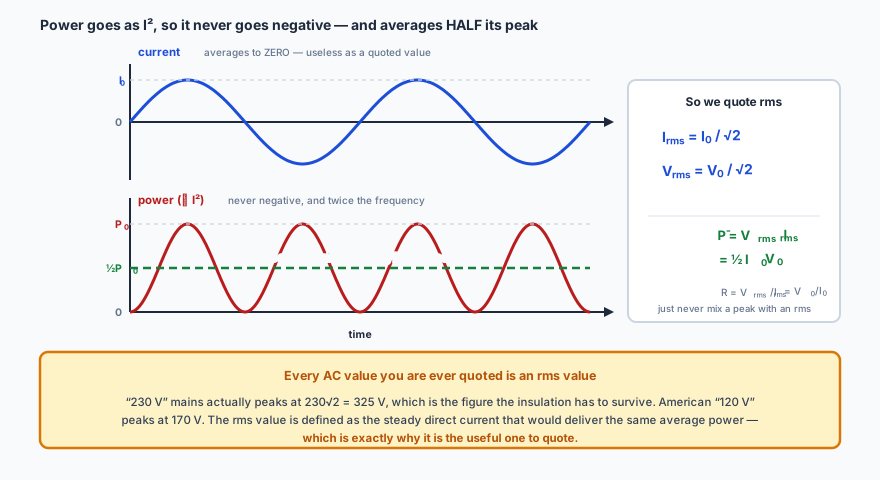
power it can deliver, and power depends on \( I^{2} \), which is never negative.
The power curve is a \( \sin^{2} \) curve, not a sine: always positive, and averaging exactly half its peak. That factor of a half is where the \( \sqrt{2} \) comes from.
The root mean square value is defined so that it behaves like a steady direct
current would: it is the square root of the mean of the square. For a sinusoid that works out to
Average power\( \bar{P} = V_{\text{rms}}I_{\text{rms}} = \tfrac{1}{2}I_0V_0 \)
Quoted AC values are always rms values. European mains at “230 V” is
230 V rms — its peak is \( 230\sqrt{2} = 325 \) V, which is what the insulation has to
withstand. In the USA “120 V” means a peak of 170 V.
Resistance behaves itself throughout: \( R = V_{\text{rms}}/I_{\text{rms}} = V_0/I_0 \), so it
does not matter which pair you use as long as you do not mix them.
✏️Worked example 5 — a lamp on the mains
A 60 W lamp runs from a 230 V (rms) mains supply. Find the rms current, the peak current, the peak
voltage and the peak power.
rms current. Average power is \( V_{\text{rms}}I_{\text{rms}} \), so
\( I_{\text{rms}} = 60/230 = 0.26 \) A.
Peaks. \( I_0 = \sqrt{2} \times 0.261 = 0.37 \) A and
\( V_0 = \sqrt{2} \times 230 = 325 \) V.
Exactly twice the 60 W it is sold as — and it has to be, since the average
of the \( \sin^{2} \) power curve is half its peak. So the lamp really does draw 120 W a
hundred times a second and nothing in between; “60 W” is the steady power that would
do the same job. Note also that using the peak voltage with the rms current, or the other way
round, would give an answer \(\sqrt{2}\) out — the commonest slip here.
🌱Eddy currents
Everything so far assumed a wire. Change the flux through a solid lump of metal and the
induced currents still flow — in closed loops within the metal itself. These are eddy
currents, and they do exactly what Lenz’s law says: oppose the relative motion, while
dissipating energy as heat.
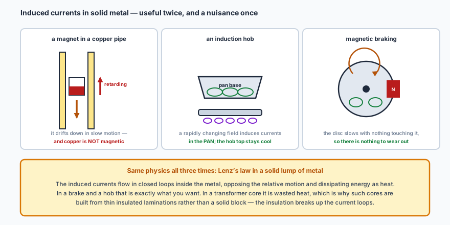
The same physics is useful in a brake, essential in an induction hob and a nuisance in a transformer core — where it is suppressed by building the core from thin insulated laminations that break up the loops.A magnet falls slowly down a copper pipe, and copper is not magnetic. That is the
point of the demonstration. Nothing is attracting the magnet; the currents induced in the pipe wall
create their own field that opposes the change, and the retarding force grows with speed until it
nearly balances the weight. Drop an identical non-magnetic slug down the same pipe and it falls
normally — which is the control that shows the effect is induction and not friction.
🔌Self-induction: a coil opposes its own current
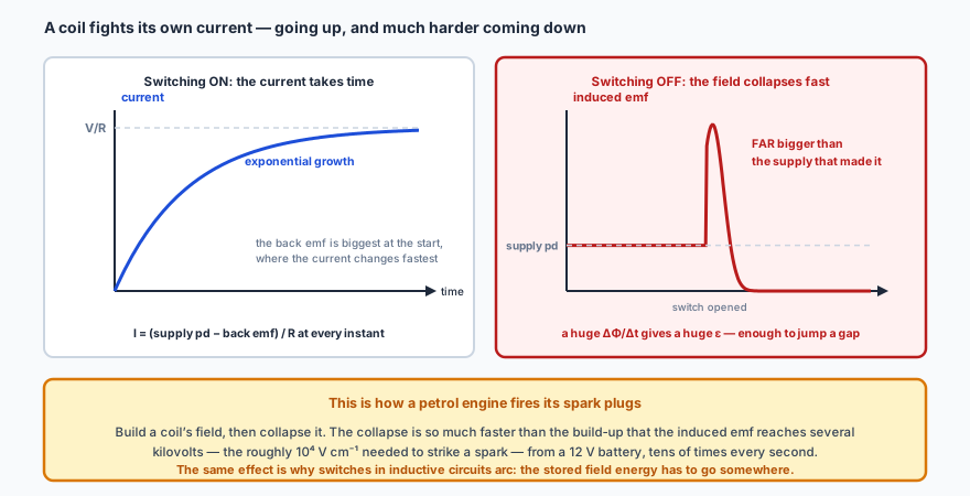
Connect a coil across a battery and the current does not jump instantly to \( V/R \). It takes
time to get there, and the reason is Faraday and Lenz applied to the coil by itself.
As the current grows, so does the coil’s own magnetic field, so the flux through its own
turns is changing — and a changing flux induces an emf in that same coil. This
is self-induction, and by Lenz’s law the induced emf opposes the change that
caused it. While the current is building up, the induced emf acts against the build-up, which is why
it is called a back emf.
At any instant the current is set by what is left over: \( I = (\text{supply pd} - \text{back emf})/R \). The back emf is largest at the start, when the current is changing fastest, and dies away as the current levels off.
Switching off is the dramatic half. The field collapses far faster than it was
built, so \( \Delta\Phi/\Delta t \) is enormous and the induced emf can be very much
larger than the supply that created it — large enough to jump a spark gap. That is
exactly how the spark plugs in a petrol engine are fired: a coil’s magnetic field is built up
and then collapsed, tens of times a second, and each collapse produces the several kilovolts needed
to ignite the fuel.
Energy is stored in the magnetic field, and it has to go somewhere. Building the
field took energy from the supply; collapsing it gives that energy back, and if you open a switch
the only path available may be through the air. This is why switches in inductive circuits arc, why
you should never break the circuit of a large electromagnet casually, and why the spark-plug trick
works at all. The IB course does not ask for the mathematics of the build-up — it is another
exponential, like radioactive decay — but it does ask for this reasoning.
🔭See it happen
PhET, Faraday’s Law and Generator. Move the magnet
through the coil at different speeds and watch the meter: the emf tracks the speed, not the
position. Then hold the magnet perfectly still inside the coil, where the flux is largest of all,
and watch the meter read exactly zero — which is the whole of Faraday’s law in one
observation.
📝Practise
Work through these, then reveal the answer. Each question targets a different objective from the list above.
1. A single loop of area \( 2.5\times10^{-2} \) m\(^{2}\) lies in a field of 0.40 T, at 30° to the normal. Find the flux.
\( \Phi = BA\cos\theta = 0.40 \times 2.5\times10^{-2} \times \cos 30^\circ = 0.40 \times 2.5\times10^{-2} \times 0.866 = 8.7\times10^{-3} \) Wb. Had the question said 30° to the plane of the loop, the angle to the normal would be 60° and the answer would be \( 5.0\times10^{-3} \) Wb instead — always check which the question means.
2. State the flux linkage for that loop if it is replaced by a 300-turn coil of the same area in the same position.
\( N\Phi = 300 \times 8.7\times10^{-3} = 2.6 \) Wb. Each turn links the same flux, so the linkage is simply \(N\) times greater — which is why coils rather than single loops are used everywhere that a usable emf is wanted.
3. The flux through each turn of a 150-turn coil changes by \( 8.0\times10^{-4} \) Wb in 0.020 s. Find the average emf induced.
\( \varepsilon = N\dfrac{\Delta\Phi}{\Delta t} = 150 \times \dfrac{8.0\times10^{-4}}{0.020} = 6.0 \) V. Note that the flux itself is tiny; what produces a usable 6 V is the number of turns and the shortness of the time.
4. A bar magnet is pushed north-pole-first into a coil. State the polarity of the coil’s near face, and hence the direction of the induced current as seen from the magnet.
The near face becomes a north pole, so that it repels the approaching magnet and opposes the change. Seen from the magnet, the induced current therefore flows anticlockwise (by the right-hand grip rule applied to the coil: curl the fingers with the current and the thumb gives the north pole, which must point back at the magnet). Withdraw the magnet and everything reverses: the near face becomes a south pole and the current runs clockwise, now attracting the magnet and again opposing the change.
5. Explain why Lenz’s law must take the form it does, in terms of energy.
Suppose the induced current helped the motion instead of opposing it. The magnet would then accelerate; the flux would change faster; a larger current would be induced; the magnet would be pushed harder still. Its kinetic energy and the electrical energy in the coil would both grow without limit and without anything being supplied — energy from nothing, which is impossible. So the current must oppose the change. The work done pushing the magnet against that opposition is exactly the electrical energy that appears: Lenz’s law is conservation of energy in the language of induction.
6. A rod of length 0.25 m slides along rails at 3.0 m s\(^{-1}\) perpendicular to a 0.60 T field. Find the emf, and the current and retarding force if the circuit has resistance 1.5 Ω.
\( \varepsilon = BvL = 0.60 \times 3.0 \times 0.25 = 0.45 \) V. Then \( I = \varepsilon/R = 0.45/1.5 = 0.30 \) A, and the force on the current-carrying rod is \( F = BIL = 0.60 \times 0.30 \times 0.25 = 4.5\times10^{-2} \) N, directed opposite to the rod’s motion — Lenz’s law. Check the energy: mechanical power \( Fv = 0.135 \) W, electrical power \( \varepsilon I = 0.135 \) W. They match exactly, as they must.
7. An aircraft of wingspan 25 m flies horizontally at 250 m s\(^{-1}\) where the vertical component of the Earth’s field is \( 4.0\times10^{-5} \) T. Find the pd between the wingtips, and explain why no current flows.
\( \varepsilon = BvL = 4.0\times10^{-5} \times 250 \times 25 = 0.25 \) V. Only the vertical component counts, because \(B\), \(v\) and \(L\) must be mutually perpendicular and the wings are horizontal and across the motion. No current flows because there is no complete circuit — the emf exists across the wingtips but there is no conducting path through the air to return the charge.
8. A coil of 80 turns and area \( 1.5\times10^{-2} \) m\(^{2}\) rotates at 25 revolutions per second in a 0.25 T field. Find the peak emf.
\( \omega = 2\pi f = 2\pi \times 25 = 157 \) rad s\(^{-1}\), so \( \varepsilon_0 = NBA\omega = 80 \times 0.25 \times 1.5\times10^{-2} \times 157 = 47 \) V. Using 25 in place of \(\omega\) would give 7.5 V — wrong by exactly \(2\pi\), which is the classic slip in this calculation.
9. Sketch how the output of that generator changes if (a) the field is doubled, (b) the rotation rate is doubled.
(a) Doubling \(B\): the peak emf doubles, to 94 V. The period is unchanged, so the graph has the same shape stretched vertically. (b) Doubling \(\omega\): the peak emf doubles as well, since \( \varepsilon_0 = NBA\omega \), and the period halves — so twice as many cycles fit into the same time and each one is twice as tall. The distinction is the point of the question: \(B\) changes only the height, \(\omega\) changes the height and the timing together.
10. A small bar magnet is dropped through a vertical coil connected to a datalogger. Sketch the emf against time, and explain why the second peak is taller and narrower than the first.
Two pulses of opposite sign, with a moment of near-zero between them while the magnet is fully inside and the flux is momentarily not changing much. The second pulse is taller and narrower because the magnet has accelerated under gravity: it leaves faster than it entered, so the flux changes more quickly (a bigger emf) over a shorter time (a narrower pulse). The two pulses have opposite signs because the flux is increasing on the way in and decreasing on the way out, so the induced current opposes each in turn. The areas under the two pulses are equal, since each equals the same total flux change.
🔗Go deeper — other people’s work
These are external resources, not mine. If one stops working, tell me and
everything above it on this page still stands.
HyperPhysics — Faraday’s law and Lenz’s law
The Physics Hypertextbook — electromagnetic induction